4-Way Switching For Your Tele
We get asked about 4-way Switching a lot. It’s a simple mod that puts your pickups in Series instead of Parallel on your Telecaster. Using the 4-way switching modification, you can get a unique, beefy tone with both pickups, adding a new dimension to your favorite guitar.
Table of contents
The Difference Between Series and Parallel Wiring For Guitar
Parallel Wiring For Guitar Pickups
Most guitar wiring configurations feature parallel wiring. It’s the standard operation of a Stratocaster or Telecaster, yielding the famous “quack” tone that is so well known. Parallel wiring features individual outputs for pickups – each pickup has its path to the output. For instance, the White (hot) leads connect to the switch, and the Black leads attach to Ground. It provides the shortest possible distance to the output jack.
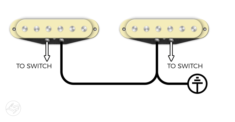
You might have noticed a volume drop when you switch between pickups in the middle positions. With parallel wiring, the perceived sound decreases when combined with another pickup.
For instance, if you only selected your Bridge pickup, it’s output is 100%. When combined with another pickup, say, the Middle pickup, it’s output seems to drop by approximately 25%. The combination of the Bridge and Middle might result in a total combined output of, say, 50%.
Series Wiring For Guitar Pickups
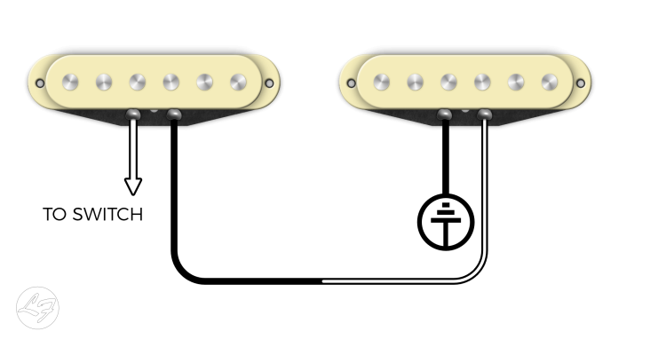
In series wiring, the output of one pickup connects to the input of the next. This connection means the current flows through each pickup in sequence, from one to the next, before it reaches the output. Series wiring gives the signal a much longer distance to travel, resulting in a beefier tone with increased output. When wiring your pickups in series, the combined signals would equate to roughly 200% or twice the output.
HOW TO WIRE 4 WAY SWITCHING For Telecaster
With a 4 Way Switch, you get the following switching capabilities:
- The Bridge
- Bridge and Neck in Parallel
- Bridge and Neck in Series
- The Neck
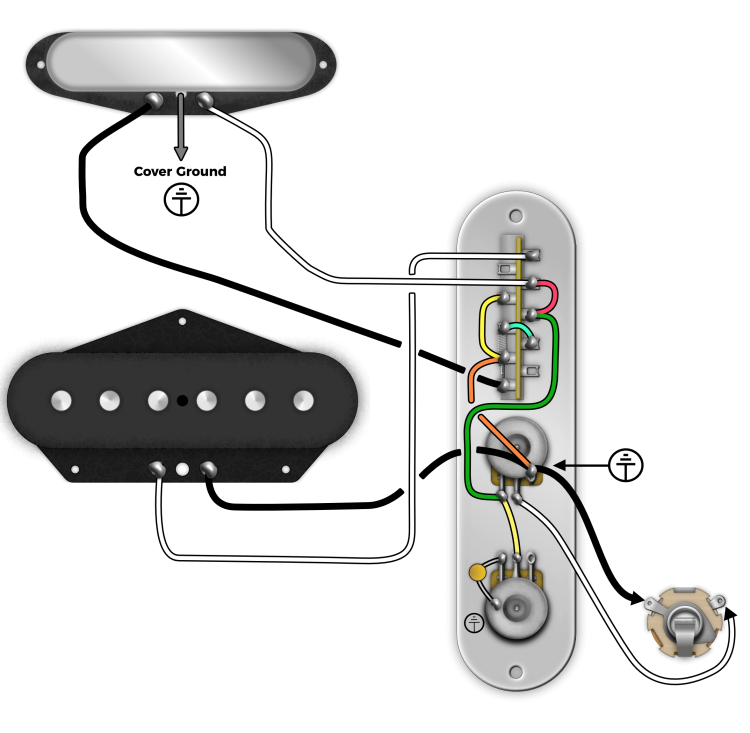
To wire it up, take a look at the following diagram:
Note: If your Neck Pickup has a cover, you will need to separate the jumper connecting the cover to ground and run a separate wire off of the cover to be grounded separately. For a How-To, check out our guide here.
How 4-Way Switching For Telecaster Works
Position 1: Bridge Only
Neck White = Connected To Output
Neck Black = Connected to Nothing*
*(Since this is the coil wire, the Neck pickup doesn’t have continuity)
Bridge White = Connected to Output
Bridge Black = Hard Ground to Pot
Position 2: Bridge & Neck Parallel:
Neck White = Connected To Output
Neck Black = Ground
Bridge White = Connected To Output
Bridge Black = Hard Ground To Pot
Position 3: Bridge & Neck Series:
Neck White = Connected To Output
Neck Black = Bridge White
Bridge White = Neck Black
Bridge Black = Hard Ground To Pot
Position 4: Neck Only
Neck White = Connected To Output
Neck Black = Ground
Bridge White = Connected To Nothing
Bridge Black = Hard Ground To Pot
If you know this is the mod you would like to do, you can order our pickups with a “3-Wire Neck“. What we will do is give you a lead that runs off of the cover. If you already have a Tele Neck and want to convert to a 4-Way Switch, you will need to solder a wire to your cover and remove the ground connection from your coil. Basically, clip the jumper wire that grounds your cover to your black lead. To see how this mod is performed, check out our guide here: Convert your Tele Neck into a 3-Wire Neck

We hope you found this article helpful! Give us a call or shoot us an email with any questions.