July Mod Of The Month: Blender And Gradual Tap Madness!
Last month we talked about our “Gradual Tap” mod. If you haven’t seen this, go back and check that one out – we’ll be using 2 of them in this […]

We get asked about 4-way Switching a lot. It’s a simple mod that puts your pickups in Series instead of Parallel on your Telecaster. Using the 4-way switching modification, you can get a unique, beefy tone with both pickups, adding a new dimension to your favorite guitar.
Most guitar wiring configurations feature parallel wiring. It’s the standard operation of a Stratocaster or Telecaster, yielding the famous “quack” tone that is so well known. Parallel wiring features individual outputs for pickups – each pickup has its path to the output. For instance, the White (hot) leads connect to the switch, and the Black leads attach to Ground. It provides the shortest possible distance to the output jack.
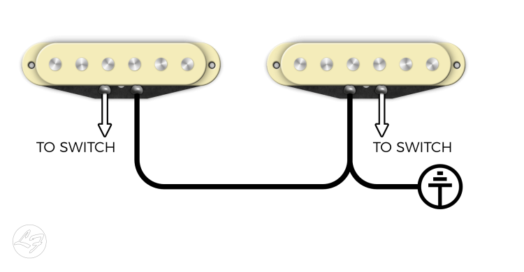
You might have noticed a volume drop when you switch between pickups in the middle positions. With parallel wiring, the perceived sound decreases when combined with another pickup.
For instance, if you only selected your Bridge pickup, it’s output is 100%. When combined with another pickup, say, the Middle pickup, it’s output seems to drop by approximately 25%. The combination of the Bridge and Middle might result in a total combined output of, say, 50%.
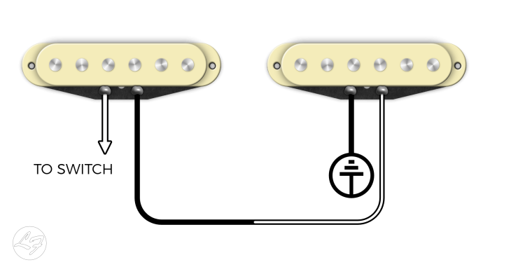
In series wiring, the output of one pickup connects to the input of the next. This connection means the current flows through each pickup in sequence, from one to the next, before it reaches the output. Series wiring gives the signal a much longer distance to travel, resulting in a beefier tone with increased output. When wiring your pickups in series, the combined signals would equate to roughly 200% or twice the output.
With a 4 Way Switch, you get the following switching capabilities:
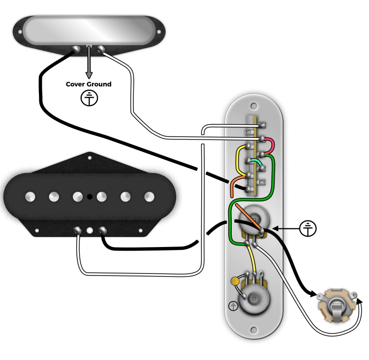
To wire it up, take a look at the following diagram:
Note: If your Neck Pickup has a cover, you will need to separate the jumper connecting the cover to ground and run a separate wire off of the cover to be grounded separately. For a How-To, check out our guide here.
Neck White = Connected To Output
Neck Black = Connected to Nothing*
*(Since this is the coil wire, the Neck pickup doesn’t have continuity)
Bridge White = Connected to Output
Bridge Black = Hard Ground to Pot
Neck White = Connected To Output
Neck Black = Ground
Bridge White = Connected To Output
Bridge Black = Hard Ground To Pot
Neck White = Connected To Output
Neck Black = Bridge White
Bridge White = Neck Black
Bridge Black = Hard Ground To Pot
Neck White = Connected To Output
Neck Black = Ground
Bridge White = Connected To Nothing
Bridge Black = Hard Ground To Pot
If you know this is the mod you would like to do, you can order our pickups with a “3-Wire Neck“. What we will do is give you a lead that runs off of the cover. If you already have a Tele Neck and want to convert to a 4-Way Switch, you will need to solder a wire to your cover and remove the ground connection from your coil. Basically, clip the jumper wire that grounds your cover to your black lead. To see how this mod is performed, check out our guide here: Convert your Tele Neck into a 3-Wire Neck
We hope you found this article helpful! Give us a call or shoot us an email with any questions.

102 Comments For This Post
Want to chime in to the conversation? Please do so! Please respect others.
I am new to soldering so sorry if this is a dumb question- How does the wiring change if the volume pot has S-1 phase/out-of-phase switching? I have a Vintera 60s Modified tele, and am planning on changing the pickups out for pure vintage 64’s. Thanks in advance, I appreciate the help.
It’s a good question. Series puts the two pickups together into one pickup, like a big humbucker. Phase Reversing reverses the phase of one pickup so that the pickups are out of phase with each other, giving it that iconic out of phase sound that some like, and others don’t. The wiring shouldn’t really change other than one pickup usually goes to the S1 Switch before going to the 4-way blade switch. You’ll need to consult a Fender Diagram for that.
Hello! I’m set to build a Tele with 4-way switching, with a used older Gibson p90 in the neck and a regular Fender Tele bridge pickup. The p90 has one white wire, one black wire, and bare silver shielding surrounding the (insulated) black wire. At present, the white and black wires are coming out of the pickup, while the shielding surrounding the black wire appears to have been soldered to something on the pickup in the past (solder blob on shielding), but is not currently connected to anything on the pickup, such as the base plate. I am unsure as to what to connect where. I tried soldering it to the base plate, but the solder is not wanting to adhere to this base plate, no matter how hot I get the solder… which leads me to think that perhaps that is not where it goes?
Do I treat the white as hot, the black as ground, and the cover as additional ground, or is there some other scheme? I ask, since sometimes black is hot on some pickups. I also am not clear on whether the shielding needs to be connected to the p90 base plate, or insulated from it, and whether the shielding and one of the wires (the black one?) are meant to be joined at ground. Any suggestions would be gratefully accepted. Thanks!
Hey Kagan, I would treat White as Hot, Black & Shield is ground. For the baseplate, you might want to get some sandpaper and sand the finish to get the solder to stick. I would definitely connect the shielding to the baseplate, which will ground the screws and chassis of the pickup.
Can you use a 4-Way Switch in a Control Plate with a Neck and Bridge Wide Range Humbucker? Looks like the 2-Conductor wiring on the Neck would work just like it would with a Tele neck pickup where the cover ground wire is added. For the bridge pickup, would I just ground the two ground wires in the same place together as I would for a Tele bridge pickup?
Hey Michael, yes you can – you would need 2-Conductor with shield wiring on at least the Neck humbucker. The Bridge Humbucker would get wired like a standard Bridge, and the Neck humbucker would get wired according to the 4-way switching Diagram. Heads up – putting two Wide Range Humbuckers in series will be a very unique sound!
Which 4-way switch is being used here? I did exactly like showed here, pickups working, neck pickup has 3 wires etc. But neck position is not working. I have re-done everything twice and still the neck pickup is mute. Can you please help?
Everything is checked so the only reason is that the switch is not working the same way.
I believe this post uses an Oak Grigsby 4-way switch.
Hello Tyler!
I’m Steve Bloom, guitarist and repairman here in NYC.
I have a Tele with a Humbucker in the Neck, Single coil bridge with 3rd wire mod.
I have a wiring issue with the 4-way switch. Can you help?
I have a push/pull for the neck humbucker, but it does strange things when I pull the switch.
I also added an out of phase mini toggle, but on 2 of the settings it cuts out the volume.
I have a diagram I can send you, if you feel you could help. thanks!!
I tried this wiring. Love the combo of flavours but I get a horrendous buzz in position 1 and 3 (bridge and series combo) if I’m not touching any metal.
Hey Steve, you have a grounding issue. Read our article on diagnosing grounding issues. If you have a multimeter, this process is super easy!
Hi, I tried this mod and it works fine on positions 1,2 and 3. At the position 4 (neck only) I got no output. Any hints?
Did you remove the jumper wire to the cover? If not, the cover is grounded and will short the signal out.
Does the tone pot not need to be connected to the ground? Am I missing something?
Hey Isaac, the Plate itself connects all the pots / parts that are screwed into it. The Volume Pot has the Ground connection and the plate connects everything else.
The one thing that would be more than super helpful when you all draw up wiring diagrams with the conventional three four and five position wafer switches is clearly marking on the diagram which terminals are the common terminals. Not all switches are made the same which basically makes it necessary.
I have been massaging my dyslexia inspired brain cramps trying to do this with the shield plate ground broken out from the bridge pickup rather than the neck because I have a humbucker with a split coil push pull in the neck, for which this diagram as-is, of course, will not work. Thanks for it anyway, I appreciate it. I’m pretty close and when it’s done I am going to publish that wiring diagram across the entire digital galaxy…
I would like a different version
1. Neck
2. Neck and bridge
3. Bridge
4. Neck and bridge in series
I have looked through tons of diagrams but have not found that one. Can you help?
Thanks in advance!
Hm, I haven’t seen that diagram before, only the opposite. I’m sorry.
Can this 4 way tele switch be done with a G&L Bluesboy, with single coil bridge and humbucker neck pickup ?
Hi Tyler I just wired up this 4way mod as shown in your diagram and turned out everything like explained beside??The position 4 or the neck alone itself is very quiet and feels like you could hardly hear it but why’s that compared to the other configuration is so silent, I took my time and did copy everything as shown or if something else I messed out please let me know ?thanks
I have a fender 50s vintera . I want to change the pickups to Texas special and go with a 4 way switch. I like the sound of the guitar now . Will I be disappointed
Hi Tyler, I have wired my 40th anniversary Squier Tele vintage edition last night, following this post. It’s so clear and helpful, thanks so much!
Series mode gives more output than any of the other 3, but its character is very close to the parallel switch. Honestly I expected more difference in tone, like less twang and more compression, but I find the difference really subtle. I guess I would fail a blind A/B test 🙂
Shall I think I made a mistake somewhere, or, since output levels are clearly different between series and parallel, should I assume that’s correct?
Hey Adam, if you experience more output, you wired it correctly. Different outputs, magnets, and winding techniques will definitely make a difference in how dark / bright your series tone is.
THANK YOU so much for this post! I just got a Vintera Modified Tele with a 4-way switch that allows you to select the bridge (pos. 1), bridge + neck in parallel (pos. 2), neck (pos. 3), or bridge + neck in series (pos. 4). I was so worried something was wrong with it because of the differences in volume between the different positions – position 4 is louder than the others, especially so when compared to position 2. Now it all makes sense, and I’m not worried my beautiful new Tele is broken anymore ? Thanks for the clear explanation!
Anytime 🙂
I have noticed with the 4 way it seems to have increased my output even with one pick up at a time , more so than with the other teles that are wired standard . I use Area hot Ts in all of them but the one that’s 4 way seems hotter all the way around ! Is it just me ? some think I’m crazy but I swear it’s a noticeable difference . Am I crazy ?
how is that one wired? you have a recomended diagram for the area hot Ts?