How To Optimize Your Pickup’s String Balance
Optimizing your guitar's tone is as simple as adjusting your pickups' string balance. These steps help you get the most out of your pickups.

3-Way, 4-Way, 5-Way, Toggle, Blade, Rotary – There’s a lot of switches available for your electric guitar. Some come in a variety of designs and can introduce some new functionality to your guitar. These little connectors are powerful when you know how to use them, so let’s learn how they work!
Today, we’re going to talk about Blade Switches. Blade Switches are the most common variety of switch, used a lot on Stratocasters and Telecasters, primarily. With understanding the Blade Switch, you can customize how your electric guitar’s pickups behave and sound; making your guitar even more unique than it is. Let’s dive in!
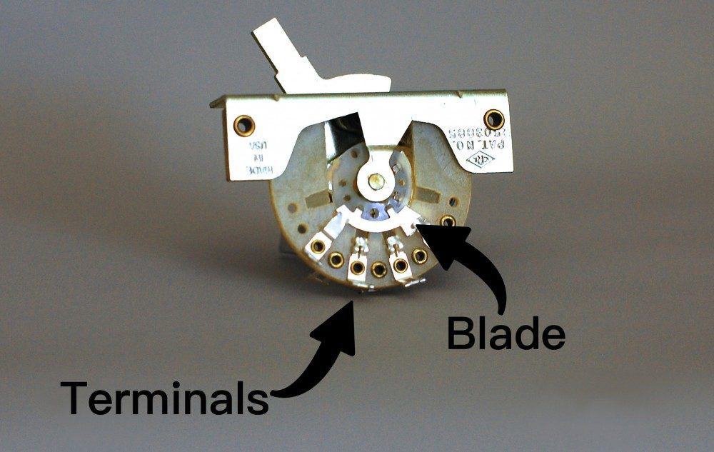
The most important thing to note about the switch is that it’s a connector. Depending on how you have it wired, its’ sole purpose is to send your signal somewhere. It does this by using the Blade to wipe across the Terminals. When the blade connects to the terminal, the signals join through to the path you’ve designed.
See below to see how the terminals are laid out: There are two sides of the switch, Side A, and Side B. These sides are entirely independent of each other, meaning A1 can’t be connected to B0 unless a jumper is activating both sides of the switch (more on this later).
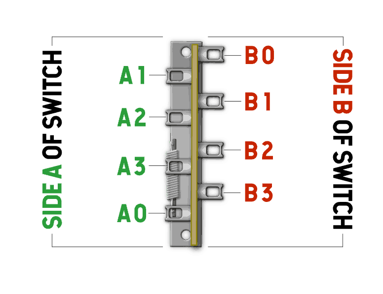
You can see that the switch has 2 Sides, and 4 Terminals Per Side. 1-3 are the selectable terminals, and the 0 is your common – it’s always connected. As we mentioned earlier, the sole purpose of the switch is a connector. Depending on what type of switch you have, all that is happening is the blade connecting Lugs 1-3 to Lug 0.
For example, if you had a neck pickup wired up to A3, when you select the Neck position on your switch, A3 is being connected to A0. If you wired A0 to your volume pot for output, that’s how the switch would connect your Neck pickup through the output.
5-Way blade switching is the most uncomplicated blade switch to comprehend, which is why we’re going to start here. The Blades can choose two terminals at the same time on the same side. The 5-Way Blade Switch looks a lot like the 3-Way Blade, except it has a slightly larger wiper blade to choose more than one terminal at the same time. This enlarged blade is useful for selecting the Bridge and Middle pickup at the same time, to get that infamous “quack” tone.
The image below shows what terminals are connected when you’re in each position. Please note that the “0” terminals are your common connections – they are always connected.
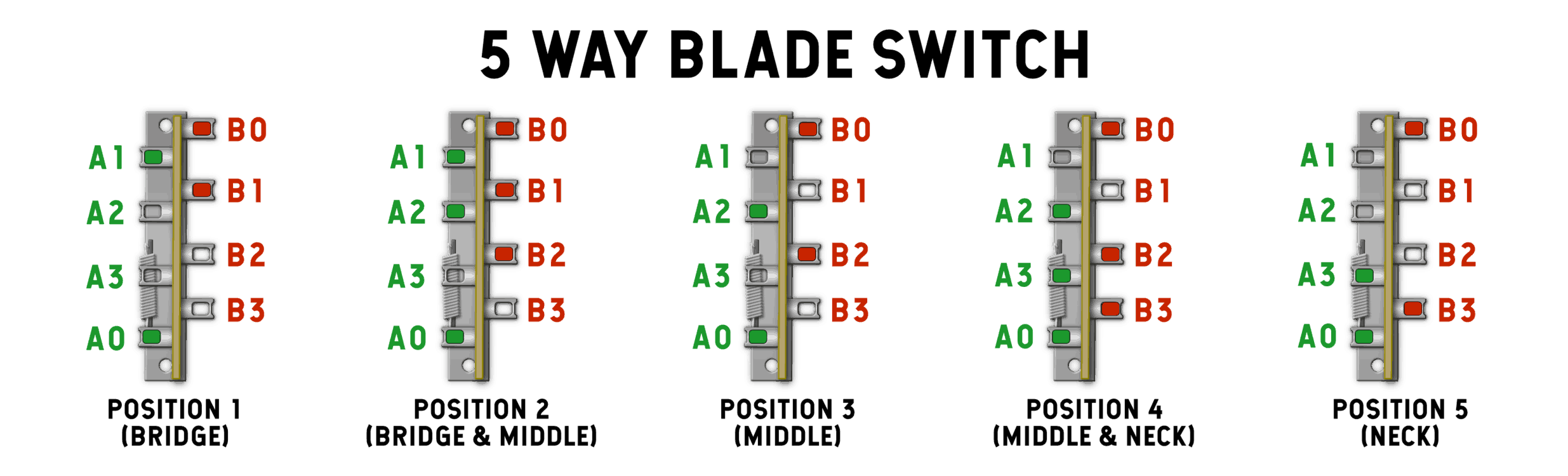
On Position 1 (Bridge), A1 and A0 connect, and B0 and B1 connect.
On Position 2 (Bridge and Middle) A1, A2, and A0 are connected, and B1, B2, and B0 connect, and so forth.
I’m sure you can see a pattern emerging here. Let’s show you a real-world example on how we wire this up:
There are many ways to wire up a Stratocaster; however, let’s take a look at a traditional one. Please note that we’ve added a jumper here! The purpose of this jumper activates (or connects) the second side of the switch. So, we have an input side of the switch where our pickups solder to, and an output side of the switch where our signal is going.
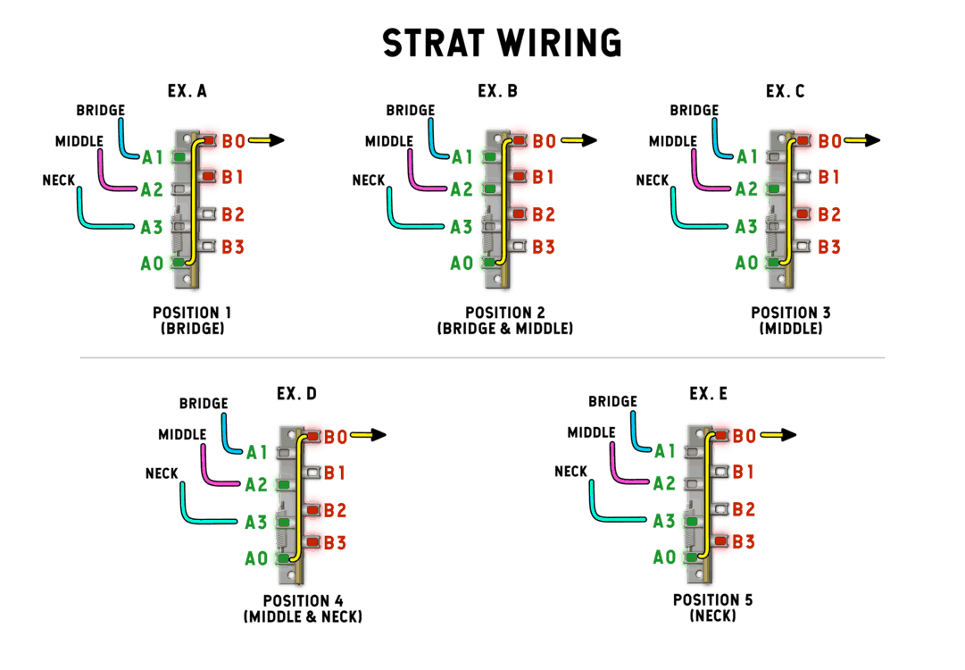
As you can see, all the pickups are entering the switch from Side A. Technically; you can use A0 as your output to the volume pot, but, you can have a lot more functionality by adding a jumper from A0 to B0!
Connecting both sides of the switch allows Side B to become an output section. So, if you have two tone controls, you can wire up the Bridge to one Tone Control and the Neck and the middle to another. You have a lot more versatility with using both sides of the switch in this way.
Before we get into additional switching, let’s talk about the other side of the switch:
By activating the Side B (or the Side A, depending on how you’re wiring this up), you can achieve some more versatility with this switch. To activate the other side, you run a jumper from one side of the switch to the other side. Doing this lets electricity move to the second side, allowing a lot more tonal combinations and output configurations. To get your signal to both sides, we run a jumper from one Common to the other Common. Let’s take a look at what we can do: As you can see
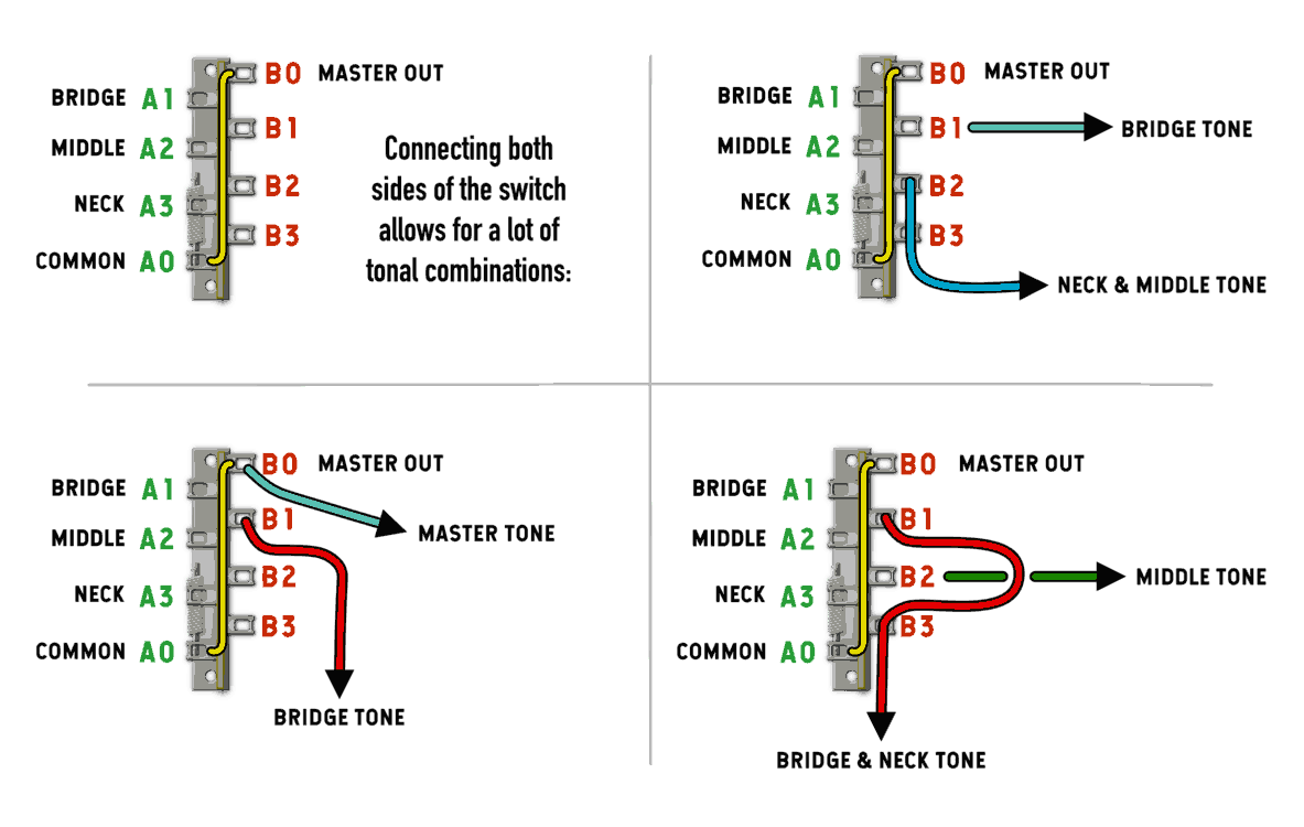
As you can see, by jumping to the next side of the switch, you can create a lot of tonal variations with your Strat. Having this second side of the switch is really useful when you have two tone controls – you can use the Neck and Middle on one tone control, and the Bridge on a separate tone control with a different value. Now that we’ve understood the basics a bit and talked about some real Stratocaster examples, let’s get into 3-Way Switching:
The 3-Way Blade switch is one of the original switches for the guitar. It was introduced on the original 1950’s Broadcasters with two pickups and solidified with the Telecaster in 1951. The 3-Way Switch, like the 5-Way Switch, is comprised of 2 sides, with 4 terminals on each side. The only difference here is the size of the blade that wipes the terminals. The 3 Way Blade only connects one terminal at a time, where the 5-Way blade switch can connect two terminals at a time.
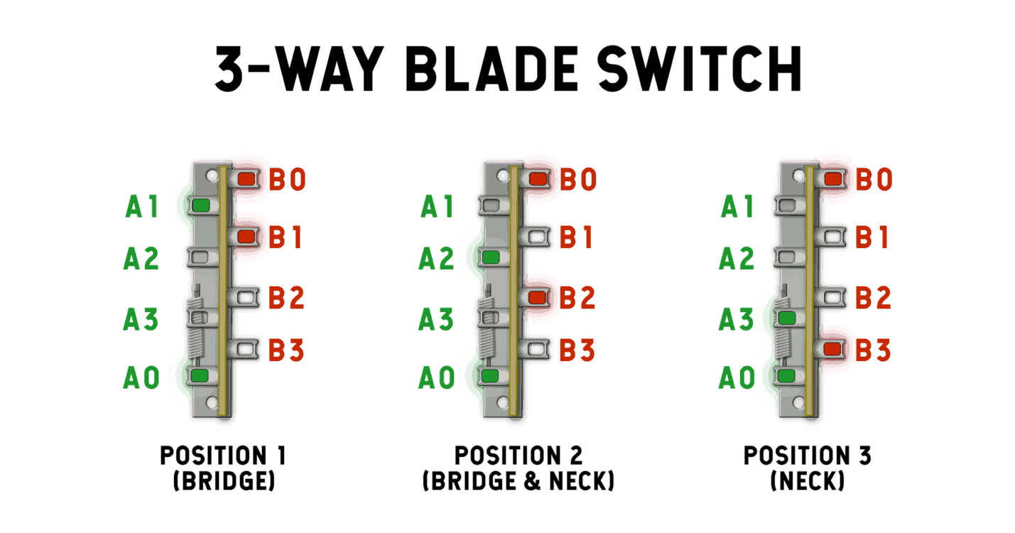
This should look familiar! The “0”‘s are always connected, and the blade selects one terminal at a time. So, even though this seems easier, there are a few challenges presented when using 2 pickups – let’s take a look:
There’s a challenge when using a 3-Way switch with a 2 pickup guitar: the blades only choose one terminal at a time. 5-Way switches don’t have this problem. We can easily remedy this with a little bit of jumper Kung-Fu. There’s a lot of 3-way switch diagrams that are confusing and difficult to understand. Our favorite is much more understandable. See below for an illustration!
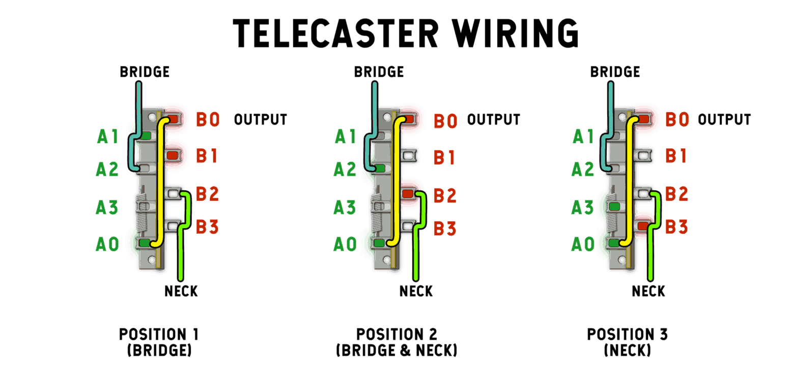
With this wiring, we wire the Bridge into both A1 and A2. We wire the Neck to both B2 and B3. We also create a Jumper from A0 to B0. B0 is our Master Output.
Position 1 (Bridge): Terminals A1 and B1 are selected. Nothing is wired up to B1, but the Bridge is wired up to A1, which is connected to A0, which is jumped to B0 Output.
Position 2: (Neck and Bridge): A2 and B2 are both selected. B2 is connected to B0, which is Output.
Position 3: (Neck Only): A3 and B3 are selected. Nothing is wired up to A3, but the Neck is wired up to B3, which is connected to B0 – Output.
Oh yeah – we’ll need a breather after that one. There are lots of ways to wire the switch up, and you can experiment with other and new creative ways to re-route your pickups signals. We hope that this article has been comprehensive as well as easy to understand! Until next time, Cheers!

39 Comments For This Post
Want to chime in to the conversation? Please do so! Please respect others.
Howdy,
Is it possible to change the three way bass switch (1 precision pup, 2 blend 50/50, 3 bridge) on a five way switch to provide different blends on the 2 & 4 spots?
1) Precision
2) 75% Precision / 25% Bridge
3) 50/50 Blend
4) 25% Precision / 75% Bridge
5) Bridge
If so, I’d appreciate all the help I can get, lol!
Best,
OttO
I have one dimarzio 4-cable-humbucker, two cables for each coil; with a 3-way switch blade I would like to get the two coils connected in series at position one, silence at position two and the two coils conected in parallel at position 3 ¿Is that possible?
As it turns out, you would need a Super Switch for something like that. We don’t make diagrams for those.
Hi, how can I use this blade switch to conect, like Ibanez, HSH, but I need to conect neck & bridge in position 4. Thank you!
You’ll need a super switch to make that happen.
I want to use a 4 way blade sw. to have neck on 1 neck bridge on 2 middle on 3 and bridge on 4
How can you make it so middle position of a 3-way is off, rather than both?
Hey Tyler, I believe your wiring diagrams are based on an Alpha switch configuration. I’m find out the hard way that Alpha’s are almost completely opposite of the CRL switches.
I like to recommend that you identify that so your users don’t wire up a CRL according to your diagram as the outcome won’t be as expected.
Regards – Mike
Can I use a 3 way blade switch with 3 pickups and use a push pull tone pot to activate the middle pickup in parallel with either of the other 2?
I have a telecaster project with a standard 3 way blade switch. I am looking for the 3 positions to be
Top: neck only
Middle: Bridge only
Bottom: Blend
Knobs are volume and blend
Is there a wiring diagram for this setup that you are aware of?